
Principles of Ellipsometry…(EL)
In (EM1) we explained Snell's law and Fresnel's formula, and in ( EM2) we extended these to complex numbers, thereby broadening their applicability to absorbing media. By applying this principle, it becomes possible to measure the thickness of thin films and evaluate their optical constants (refractive index, extinction coefficient, etc.), composition ratio, surface roughness, crystallinity, etc. We will show the derivation of the basic principles of ellipsometry, the analytical technology that makes this possible.
table of contents:
・Derivation of the definition of ellipsometry
・Amplitude reflectance of p-polarized and s-polarized light in an absorbing medium (review)
First, let's review the amplitude reflectance of p-polarized and s-polarized light, taking into account absorption in the medium, which is the premise of ellipsometry. The derivation process is shown in (EM2) , so only the results are shown here.
Consider the incidence of a light ray from medium 1 to medium 2, taking into account absorption in medium 2. In this case, the refractive indices of medium 1 and medium 2 are set as follows (wherein the refractive index of medium 2 is a complex number).
Refractive index of medium 1: n1
Refractive index of medium 2: n2 + jκ2
Furthermore, the incidence angle and the exit angle are defined as follows (where the exit angle is a complex number).
Incidence angle : θ
Exit angle: ξr+jξi
The diagram below illustrates this.

In this case, Snell's law, taking into account absorption in medium 2, is expressed as follows:

however,


Solving this for ξr and ξi and expressing it as a function of θ, we get the following (see (EM2) for the derivation).

… (EM2)-(11)-③-5,7, (EM2)-(11)-④-5,7

… (EM2)-(11)-③-2a,b
In this case, for n2 > n1 , the amplitude reflectance of p-polarized and s-polarized light can be expressed as follows, separated into the absolute value of the amplitude and the phase (see (EM2) for the derivation).


However, the range of arctan is set to be greater than -π /2 and less than π /2.
Definition of ellipsometry parameters
By applying (EM2)-(12)-②-2 and (EM2)-(12)-③-2, the Fresnel amplitude reflection coefficient ratio ρ defined by ellipsometry can be expressed as follows using the phase difference Δ and amplitude ratio angle ψ (these are called ellipsometry parameters):

*The definition of the sign of phase differs between the fields of physics and optics, according to their respective conventions. See (SG) for details.
However, the domain of the phase difference Δ is set to 0 ≤ Δ ≤ 2π . If the value of (1)-①-2 is outside this range, simply add 2mπ (m is an integer) and select the value of m so that it falls within the domain.
For example, when n=1.44 and κ=5.23, ψ and Δ are calculated using θ as a variable as follows:


・Description and illustration of the electric field vectors of p and s polarizations in ellipsometry.
Let us now review the electromagnetic wave formula. If the electric field vectors of p- and s-polarized incident light are Eip and Eis respectively, the electric field amplitude vectors of p- and s-polarized incident light are EAip and EAis respectively, and the wave vector of the incident light is ki , then from (EM1)-(2)-①, these relationships can be expressed as follows:

Here, the unit vector of the electric field amplitude vector of p-polarized and s-polarized incident light is defined as follows:

In this case, (1)-②-1,2 can be rewritten as follows:

Similarly, if the electric field vectors of p- and s-polarized reflected light are Erp and Ers respectively , the electric field amplitude vectors of p- and s-polarized reflected light are EArp and EArs respectively , and the wave vector of the reflected light is kr , then from (EM1)- (2)-①, these relationships can be expressed as follows:

Here, the unit vector of the electric field amplitude vector of p-polarized and s-polarized reflected light is defined as follows:


In ellipsometry, the incident light is set as follows.


(1)-④-1,2 can be rewritten as follows by applying (1)-⑧.

This is linearly polarized light tilted at π /4 (45 degrees) with respect to the p-axis (or s-axis). This state can be achieved by using a linearly polarized laser in monochromatic ellipsometry, or by passing white light through a polarizer in spectroscopic ellipsometry.
Also, (1)-⑦-1,2 can be rewritten as follows by applying (EM2)-(12)-②-2, (EM2)-(12)-③-2, (1)-①-2, and (1)-⑧.

Therefore, when viewed on the time axis, p-polarized light leads Δ/ω ahead of s-polarized light.
Based on the above, ψ and Δ can be illustrated on the time axis as follows:

Here, the electric field of the incident light is shown with the absolute value normalized to 1 in addition to the condition (1)-⑧.
In this way, a phase difference Δ occurs upon reflection of linearly polarized incident light, and the reflected light generally becomes elliptically polarized light.
The polarization changes depending on the value of Δ as shown in the diagram below. When Δ=0,π, the light is linearly polarized, and otherwise it is elliptically polarized, but the direction of rotation (clockwise and counterclockwise) is reversed before and after Δ=0,π.

Furthermore, (1)-⑪-1a and 2a can also be expressed as follows:

Therefore, when viewed on the spatial axis, p-polarized light is delayed by Δ/kr relative to s-polarized light.
Therefore, ψ and Δ can be illustrated on the spatial axis as follows:

Here again, the electric field of the incident light is normalized to 1 in absolute value in addition to the condition (1)-⑧.
・Measurement of the refractive index of bulk samples
・Representation of bulk sample complex refractive index using ellipsometry parameters
Consider the case where light is incident from medium 1 to an absorbing medium 2 with a thickness at semi-infinity. In this case, the refractive index (a complex number) of medium 2 can be determined from ellipsometry measurements, and we will explain the principle behind this.
First, the amplitude reflectance in a non-absorbent medium is shown below (see (EM1) for derivation).

Here, too, we replace the refractive index n2 and the emission angle ξ of medium 2 with the following complex numbers.

At this time, (EM1)-(4)-⑨a and (EM1)-(5)-⑨b become as follows.

In this case, the Fresnel amplitude reflection coefficient ratio ρ defined in (1)-① is expressed as follows:

Here, the refractive index ratio of mediums 1 and 2, and the cosine ratio of the angle of incidence and angle of exit at the medium interface are set as follows.

Substituting this into (2)-②, we get the following:

From this, Snell's Law states the following:
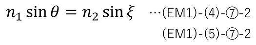
Here, too, we replace the refractive index n2 and the emission angle ξ of medium 2 with the following complex numbers.

At this time, (EM1)-(4)-⑦-2 and (EM1)-(5)-⑦-2 become as follows.

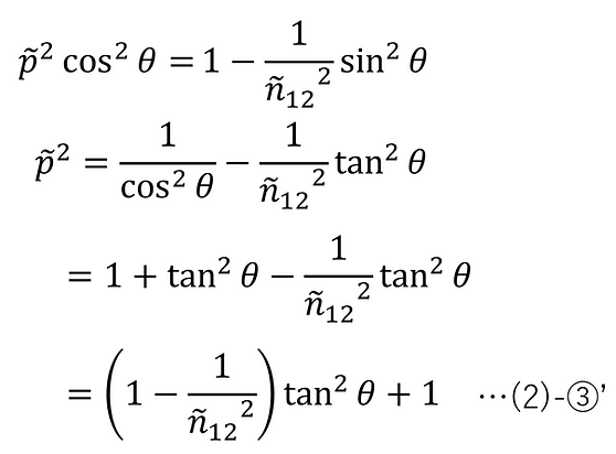
Therefore, since it is known that the formulas for trigonometric functions also hold for complex numbers, applying (EM2)-(11)-②, the cosine of the exit angle can be transformed as follows.

Substituting (2)-④ here, we get the following:
Substituting this into (2)-②', we can find p as follows.

Substituting this further into (2)-②', the refractive index ratio can be found as follows.

Therefore, the refractive index (complex number) of medium 2 can finally be determined as follows.

・Separation of the real and imaginary parts
From here, we will separate (2)-⑤' into its real and imaginary parts.
First, if we separate the ρ defined in (1)-① into its real and imaginary parts, we get the following:

Here, we set it as follows:

Using this, (2)-⑥ can be expressed as follows.

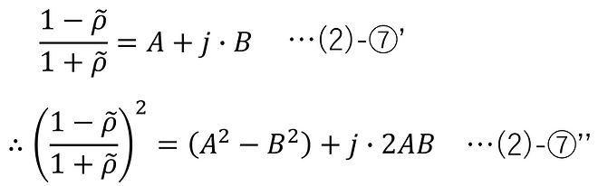
Applying this, we transform the following equation to separate it into a real part and an imaginary part.

Here, we set it as follows:

Using this, (2)-⑦ can be expressed as follows.
After squaring (2)-⑤', and applying (2)-⑦'', we can rearrange it to separate the real and imaginary parts as follows.

Here, we set it as follows:

Using this, (2)-⑨ can be expressed as follows.

Here, the complex refractive index of medium 2 was defined as follows:

However, n2 > 0 (from (EM2)-(11)-①-3)
Therefore, by applying the formula for the square root of a complex number, we obtain the following solution.

However, sgn(D) is a sign function and has the following properties.

-
Related literature
[A] Fujiwara, H. (2011). Spectroscopic Ellipsometry (2nd ed.). Maruzen Publishing.
-
Update History
-
2026-04 Added "Measurement of the refractive index of bulk samples"
-
2026-03 Newly released