Electromagnetic wave theory of light reflection and refraction (I)
~Electromagnetic treatment of non-absorbing media~ …(EM1)
*Since formula references jump around a lot, when you want to see the referenced formulas, we recommend that you view them in a duplicate separate window.
This course systematically derives various formulas for electromagnetic waves. It is recommended that you understand the entire flow.
・Description of elliptic polarization due to the p/s polarization component of electromagnetic waves incident on the interface
・Fresnel's formula for p-polarized light (reflection and Snell's law are also derived along the way)
-
Parameter definitions and relationships
First, the definitions of the parameters of the electromagnetic wave will be shown.

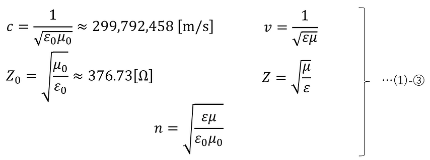
Here, the permittivity and permeability in a vacuum are the following constants:

Based on the definitions, we will show each parameter and the relationship between the parameters.
・The speed of light is the distance that light travels per unit time, and the wavelength is the distance that light travels in one vibration. Also, frequency is the number of times that light vibrates per unit time. Therefore, frequency is expressed as the speed of light divided by the wavelength. Also, angular frequency is the frequency expressed in phase.

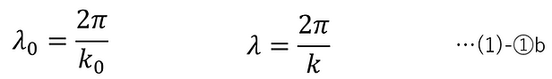
・The wave number is the number of times light vibrates per unit length, expressed in phase. Therefore, the wavelength is expressed as the value obtained by dividing the unit length by the wave number and multiplying by 2π .
・Characteristic impedance is the ratio of the electric field to the magnetic field of electromagnetic waves propagating through a transmission medium (transmission line or space).

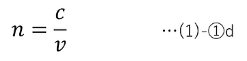
・The refractive index is the ratio of the speed of light in a vacuum to the speed of light in a medium, and has a value specific to the medium. The refractive index is always greater than or equal to 1 (except for special cases such as metamaterials).
The relationship between the permittivity and permeability and each parameter is derived from Maxwell's equations [1], and the results are as follows:
In addition, the following relationship exists between the angular frequency in a vacuum and in a medium (this relationship is derived in (3)-⑥):
Applying (3)-⑥ to (1)-① and then integrating (1)-③ with this, we obtain the following equation:

In addition, for non-magnetic media, the magnetic permeability can be treated as follows:

In this case, (1)-④ can be further rewritten as follows:
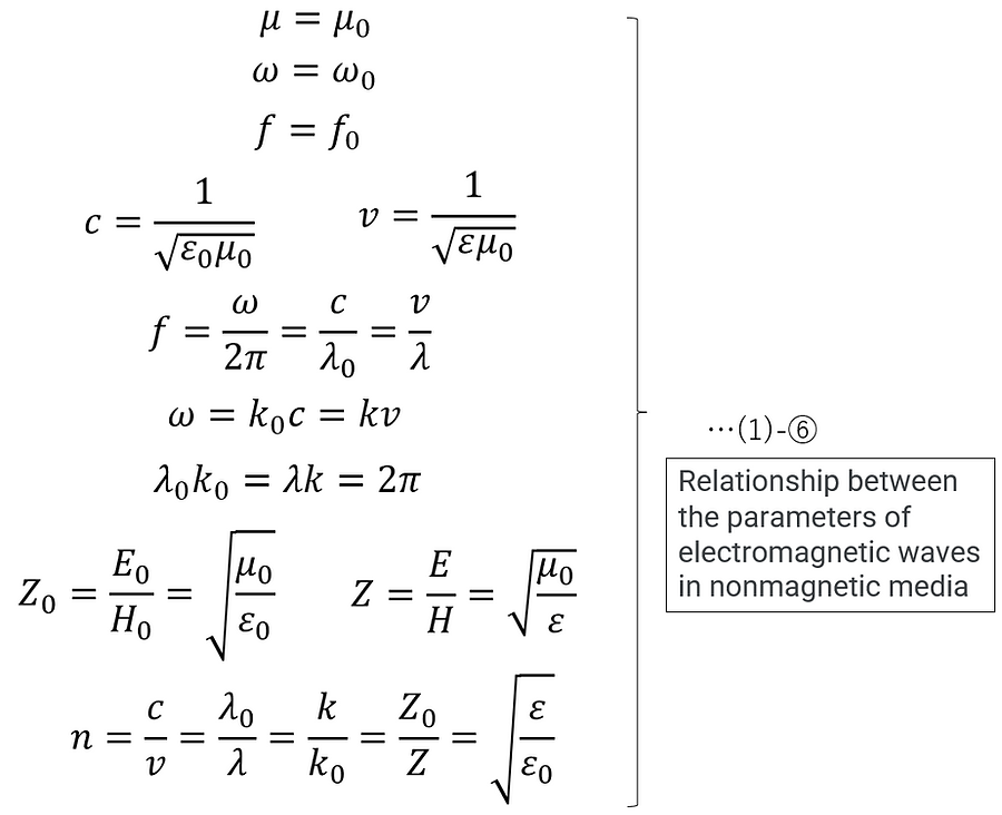
(1)-④ and (1)-⑥ are very important equations that show the relationship between the various parameters of electromagnetic waves in magnetic and non-magnetic media, respectively.
-
Mathematical expression of electromagnetic waves
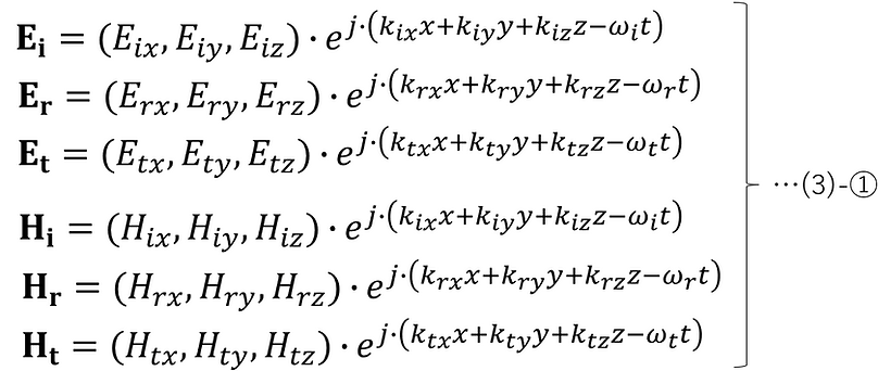
Electromagnetic waves can be expressed as follows (only the results derived from Maxwell's equations are shown)[2]:
Electric field vector:
Magnetic field vector:

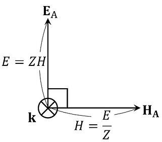
The relationship between the electric field and the magnetic field is as follows.
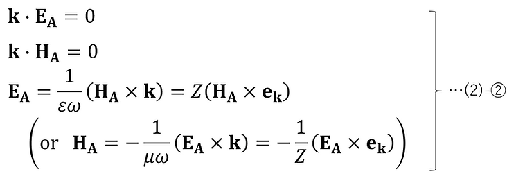
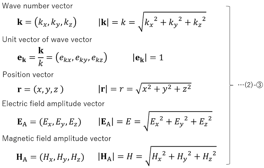
where each vector is a quantity defined as follows:
In addition, the third equation in (2)-② uses the following relationship derived from (1)-④.

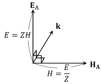
The relationship between the directions of the vectors shown in (2)-② can be illustrated as follows.
Here, the vector depth method can be expressed as follows:
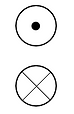
...From back to front
...From front to back
Using this, the relationship between the vector directions shown in (2)-② can be expressed as follows.
The electromagnetic wave represented by (2)-① can be illustrated as follows. Here, to avoid complicating the diagram, ekz =0, but the same consideration can be given to the case where ekz is not 0.

Moreover, the relationship between the phase lead and the electromagnetic wave lead can be illustrated as follows:
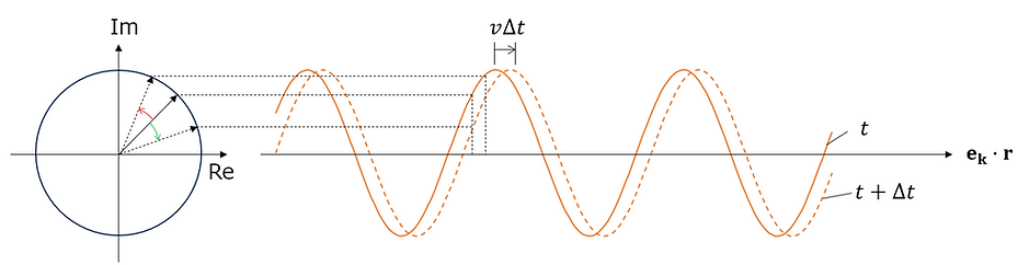
In this way, since the phases of the position advance and the time advance are in opposite directions, the signs of the position component and the time component are opposite.
*The definition of the sign of phase itself differs between the fields of physics and optics, according to their respective conventions. See (SG) for details.
-
Boundary conditions for propagation between media
As shown in the figure below, in the propagation of light between non-magnetic media, the z=0 plane is set as the boundary between the media, and we consider the transmitted and reflected light when an electromagnetic wave is incident on the boundary surface.

Here, the subscripts of each parameter have the following meanings:
i: Value for incident light
r: Value for reflected light
t: Value for transmitted light
The electric field and magnetic field of incident light, reflected light, and transmitted light are expressed as follows from (2)-①.
Now consider the boundary conditions of the electromagnetic field at the boundary surface.
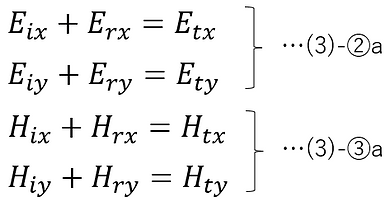
Since the tangential component of the electric field is continuous at z=0,
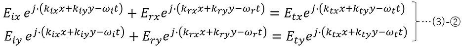
Since the tangential component of the magnetic field is continuous at z=0,

For any x, y, and t, the conditions for (3)-② and (3)-③ to hold are

In this case, (3)-② and (3)-③ will be as follows.
From (3)-④-3, the ω of incident light, reflected light, and emitted light will be expressed as a common ω without the subscript.
In addition, since ω does not depend on the medium, the following can also be said:
Here, there is no loss of generality in determining the y-axis in the direction where 𝑘𝑖𝑦 = 0.
In this case, from (3)-④-1, we get the following.
From this, if the y-axis is determined in the direction where 𝑘𝑖𝑦 = 0, it can be said that the incident light, reflected light, and transmitted light are all within the xz plane .
Furthermore, since the electric and magnetic fields can each be expressed as the sum of a component that vibrates parallel to the plane of incidence (p-polarized light) and a component that vibrates perpendicular to the plane of incidence (s-polarized light), this will be explained in the next chapter.
-
Description of elliptic polarization due to the p/s polarization component of electromagnetic waves incident on the interface
In a scenario where electromagnetic waves are incident on an interface, when the plane containing the normal to the interface and the incident light is defined as the plane of incidence, the component of the electric field that vibrates parallel to the plane of incidence is defined as p-polarized light, and the component of the electric field that vibrates perpendicular to the plane of incidence is defined as s-polarized light. This can be illustrated as follows.

In this case, any electromagnetic wave incident on the interface can be described as the sum of p-polarized and s-polarized waves, as shown below.

Here, we define the unit vector of the amplitude vector as follows.

However, the absolute value of the amplitude vector extends the concept to complex numbers as follows (this is called the complex amplitude). This is to describe the amplitude in a way that includes the relative phase difference δ between p-polarization and s-polarization.

Using this, (3')-②a,b can be rewritten as follows.

Let the scalar components (i.e., the coefficients of the unit vectors) of (3')-② a',b' be as follows.

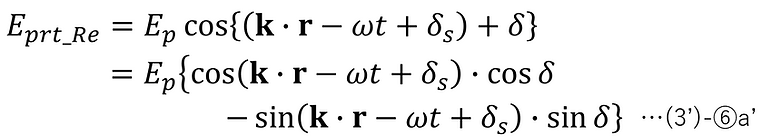
Furthermore, the real part of (3')-⑤a,b is set as follows.

Transforming (3')-⑥a results in the following:
Substituting (3')-⑥b into this, the position vector and time are eliminated, resulting in the following:

Squaring both sides, we finally obtain the following equation.

This represents an elliptical shape and shows the trajectory of the tip of the electric field vector over time as it changes at an arbitrary position vector.
Especially,
[i] When δ = 2m × π (where m is an integer),

This represents a straight line, so it is called linear polarization.
[ii] When δ = (2m + 1) × π (where m is an integer),

This also represents a straight line, so it is called linear polarization.
[iii] When δ = (m + (1/2)) × π (where m is an integer) and Es = Ep = E,

This represents a circle with radius E, and is therefore called circularly polarized light.
・Derivation of the rotation angle and ellipticity of an ellipse
Here, the elliptic shape of (3')-⑦' is assumed to be the same as the elliptic shape shown below, rotated by an angle γ with respect to the origin.

Here, a and b are the semi-major axis (or minor axis) and the minor axis (or major axis), respectively, and are assumed to take positive values.
At this point, the following can be said:

Substitute (3')-⑨ into (3')-⑦',

(3')-⑧ and (3')-⑩ are the same,

From (3')-⑩b and (3')-⑪b,

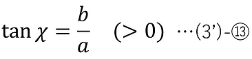
Here, the ellipticity χ is defined by the following equation.
From (3')-⑩a,c, (3')-⑪a,c, and (3')-⑫, the following is obtained.

Here, we will use the following relationship.
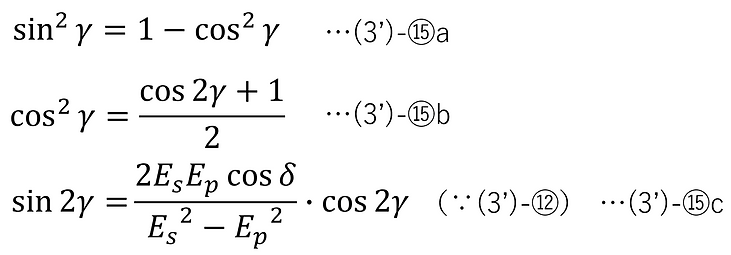
Substituting these into (3')-⑭ and rearranging, we get the following:

Here, from (3')-⑫, cos2γ can be expressed as follows.

Substituting this into (3')-⑭' and rearranging, we obtain the following:

Also, since a and b are positive values, tanχ is a positive value from (3')-⑬, and tanχ can be found from (3')-⑭ as follows.

Generally, ellipticity is expressed in the form sin2χ, and from (3')-⑭'' and (3')-⑭''', the following equation is finally obtained.

-
Fresnel's formula for p-polarized light
Consider the case where the electric field oscillates parallel to the plane of incidence (p-polarization) when light is incident on the boundary surface of a z=0 plane medium. In this case, the electric and magnetic fields of the incident light, reflected light, and transmitted light are expressed as shown in the figure below.

The subscripts 1 and 2 indicate differences in the medium, respectively.
Furthermore, since we will only be discussing p-polarization here, the subscript p will be omitted.
The directions of the electric and magnetic fields are illustrated according to (2)-②.
The propagation is assumed to occur between non-magnetic, non-absorbent media, and (1)-⑥ is applicable.
Each vector shown in the figure can be expressed in component form as follows:
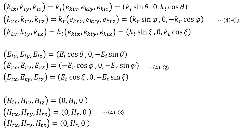
Here, from (1)-⑥,

from (4)-④-1,

In addition, from (3)-④-1 and (4)-①,

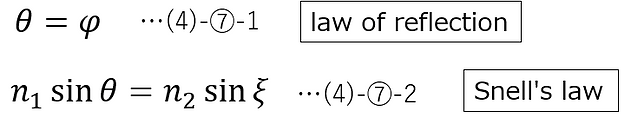
From (4)-⑤ and (4)-⑥, the following law of reflection and Snell's law can be derived.
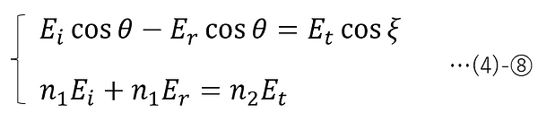
Substituting (4)-②③ (electric field and magnetic field component expression for p-polarized light) into (3)-②a, ③a (boundary condition for electric field and magnetic field amplitude), and then applying (4)-④-2 (relationship between electric field and magnetic field amplitude) and (4)-⑦-1 (law of reflection), we obtain the following:
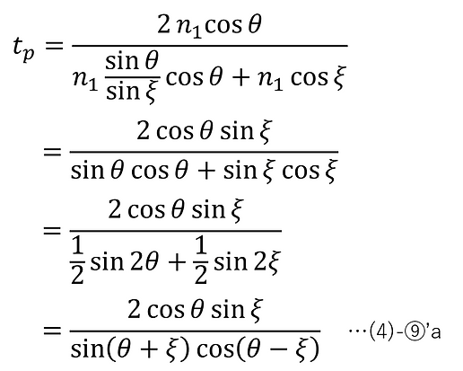
Therefore, if the amplitude transmittance is tp and the amplitude reflectance is rp , the following Fresnel formula (p-polarized light) can be obtained.

When ξ≠0, (4)-⑨ can be further expressed as follows by applying (4)-⑦-2.

When θ=0, (4)-⑦-2 gives ξ=0, and then, from (4)-⑨,

-
Fresnel's formula for s-polarized light
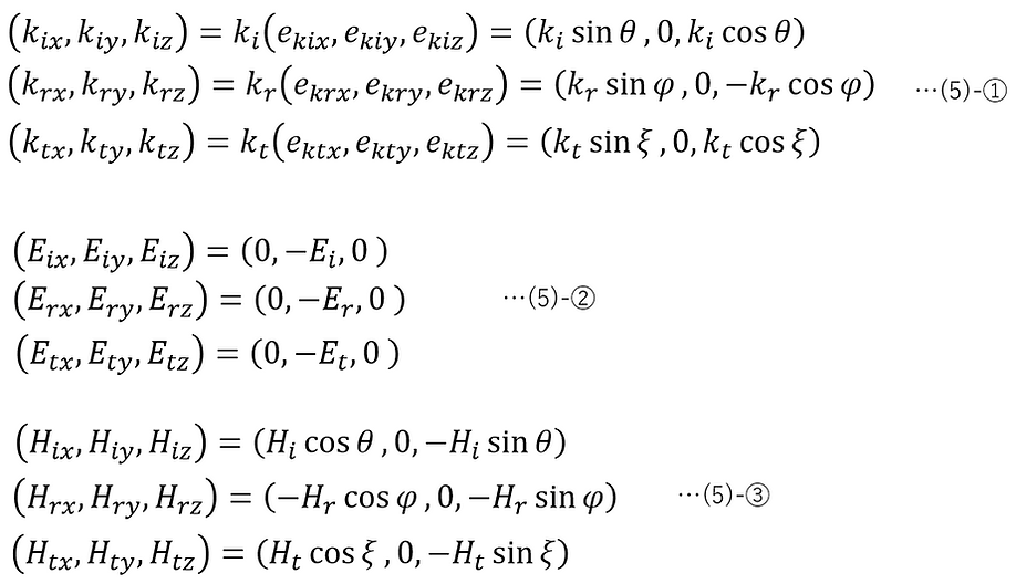
Consider the case where the electric field oscillates perpendicular to the plane of incidence (s-polarization) when light is incident on the boundary surface of a z=0 plane medium. In this case, the electric and magnetic fields of the incident light, reflected light, and transmitted light are expressed as shown in the figure below.

The subscripts 1 and 2 indicate differences in the medium, respectively.
Furthermore, since we will only be discussing s-polarization here, the subscript 's' will be omitted.
The directions of the electric and magnetic fields are illustrated according to (2)-②.
The propagation is assumed to occur between non-magnetic, non-absorbent media, and (1)-⑥ is applicable.
Each vector shown in the figure can be expressed in component form as follows:
Here, from (1)-⑥,
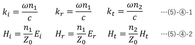
(5)-④-1,

In addition, from (3)-④-1 and (5)-①,

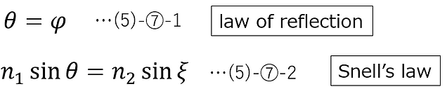
From (5)-⑤ and (5)-⑥, the following law of reflection and Snell's law can be derived.
Substituting (5)-②③ (electric field and magnetic field component expression for s-polarized light) into (3)-②a, ③a (boundary condition for electric field and magnetic field amplitude), and then applying (5)-④-2 (relationship between electric field and magnetic field amplitude) and (5)-⑦-1 (law of reflection), we obtain the following:
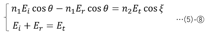
Therefore, if the amplitude transmittance is ts and the amplitude reflectance is rs, the following Fresnel formula (s-polarized light) can be obtained.

When ξ≠0, (5)-⑨ can be further expressed as follows by applying (5)-⑦-2.


When θ=0, (5)-⑦-2 gives ξ=0, and then, from (5)-⑨,
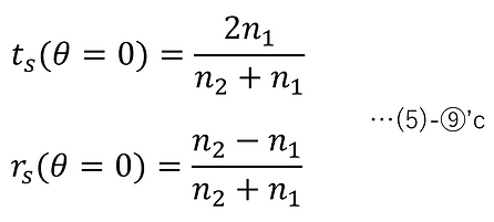
Since the normal incidence of p-polarized light and the normal incidence of s-polarized light are in the same state, it goes without saying that (4)-⑨'c and (5)-⑨'c have the same formula.
-
Transmittance and Reflectance
The volumes of the incident light, reflected light, and transmitted light passing through the infinitesimal region dxdy on the z=0 plane per unit time are dVi , dVr , and dVt , respectively. These are illustrated as follows.
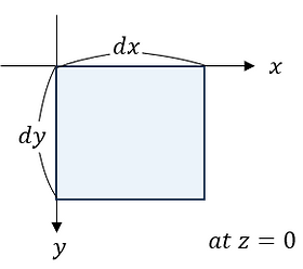
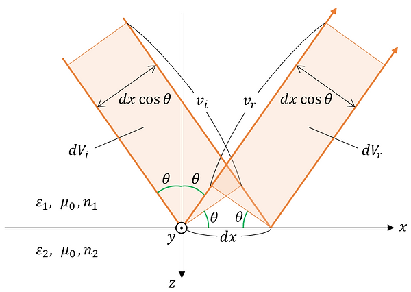
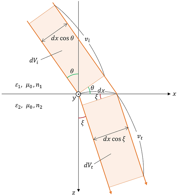
From the figure, dVi , dVr , and dVt can be expressed as follows.

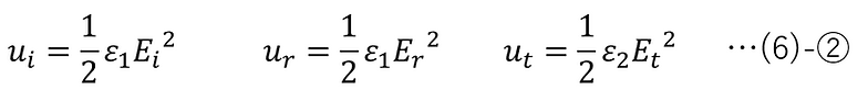
The energy densities of the incident light, reflected light, and transmitted light are expressed as follows [3]:
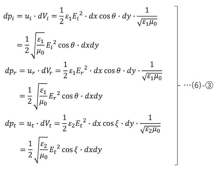
Therefore, from (6)-①, ② and (1)-⑤, the amount of energy of the incident light, reflected light, and transmitted light passing through the infinitesimal region dxdy on the z=0 plane per unit time can be expressed as follows:
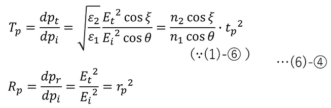
Therefore, the energy transmittance Tp and energy reflectance Rp of p-polarized light are as follows:
Substituting (4)-⑨ into this, we get :

From (6)-④', the following calculation results confirm that the law of conservation of energy is satisfied.
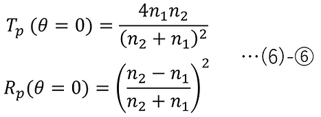
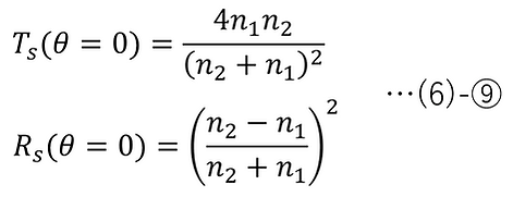
At normal incidence:
Moreover, the energy transmittance Ts and energy reflectance Rs of s-polarized light are respectively as follows:

Substituting (5)-⑨ into this, we get :

From (6)-⑦', the following calculation results confirm that the law of conservation of energy is satisfied.
For normal incidence, it is as follows. Since normal incidence of p-polarized light and normal incidence of s-polarized light are in the same state, it goes without saying that (6)-⑥ and (6)-⑨ have the same equation.
For the case of n1=1 and n2=2, if we graph (4)-⑨, (5)-⑨, (6)-④, and (6)-⑦, we get the results shown below.


When n1 > n2 , total reflection occurs as θ is increased, as will be explained later.
※Supplementary Note:
In the derivation process, typical textbooks use the Poynting vector S = E × H [4] to represent the energy flow of electromagnetic waves. However, in this paper, the energy flow is derived using the energy density and the volume passing through the interface per unit time. This is physically equivalent to the time-averaged Poynting vector, and the results are in agreement.
-
Brewster's Angle
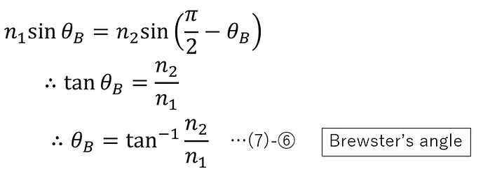
As can be seen from the graph of the incidence angle dependence of energy reflectance shown in the previous chapter, p-polarized light is not reflected at a certain incidence angle. This angle is called the Brewster angle θB , and we will derive it.
In (4)-⑨, when rp =0,

(4)-⑦-2 (Snell's law)
(7)-① and ②,
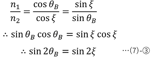
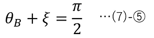
Here, the following angle conditions are considered:

The solution obtained at this time is as follows:
Again, from (4)-⑦-2 (Snell's Law),
-
Total reflection and evanescent waves
When n1 > n2 , as the angle of incident light is increased, the exit angle ξ of the transmitted light becomes π/2 at a certain angle of incidence θ. The angle of incidence at this time is called the critical angle, and according to (4)-⑦-2 and (5)-⑦-2 (Snell's Law), it is as follows for both p-polarized light and s-polarized light.

At angles of incidence greater than this, Snell's law does not have a real solution ξ. In this case, all of the incident light is reflected. This is called total reflection. When n1 > n2 , the incidence angle dependence of the energy transmittance and reflectance is as follows:

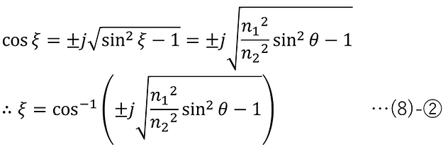
Even under the condition of total reflection, if ξ is expanded to a complex number, Snell's law can have a solution. In other words, under the condition of total reflection, sinξ is a real value greater than or equal to 1, but ξ is a complex number.
The complex solution under the total reflection condition can be found as follows.
For p-polarized light, the electric field and magnetic field of the transmitted light under the total reflection condition are as follows, substituting (4)-①, ②, and ③ into (3)-① and applying (8)-②, (4)-④-2, (4)-⑤-2, (4)-⑥, and (4)-⑦-2.

For s-polarized light, the electric field and magnetic field of the transmitted light under the total reflection condition can be obtained by substituting (5)-①, ②, and ③ into (3)-① and applying (8)-②, (5)-④-2, (5)-⑤-2, (5)-⑥, and (5)-⑦-2.
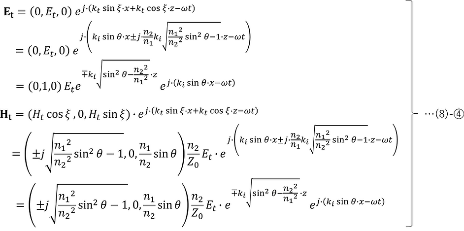
The result obtained is merely a mathematically obtained solution, but among the following z-dependent components that are common to both p-polarized and s-polarized light, the negative complex signs represent evanescent waves that actually exist physically (the positive complex signs do not exist physically).
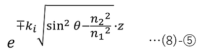
This means that the amplitude decays exponentially with respect to z, and the distance from the interface (z=0) until the amplitude decays to 1/e (penetration depth) is expressed as follows (applying ③-⑧ by transforming the equation):

Regarding the effect of the penetration of evanescent waves on the amount of reflected light (energy reflectance), substituting (8)-② into (6)-④ and ⑦ gives Rp =1, Rs =1, which shows that there is no loss of light due to total reflection. However, when substituting (6)-④ and ⑦, the value of Tp does not become zero, and the denominator of Ts becomes zero, making it impossible to calculate. This is because evanescent light is not considered in the process of deriving the formulas for Tp and Ts .
-
Stokes' Relation
In (4)-⑨ and (5)-⑨, the amplitude reflectances of p-polarized and s-polarized light when entering medium 2 from medium 1 are rp and rs , respectively, and the amplitude transmittances of that are tp and ts , respectively . What is shown here applies to both p-polarized and s-polarized light, so the subscripts p and s are omitted, and the amplitude reflectance is expressed as r and the amplitude transmittance as t .
Also, the amplitude reflectance and amplitude transmittance when light is incident on medium 1 from medium 2 on the opposite side are denoted as r' and t', respectively.
Assume that neither medium 1 nor medium 2 has absorption.
In this case, the following electric field amplitude relationship in Figure 9-1 holds.

Next, if the reflected light in Figure 9-1 is directed in the opposite direction and made to enter the interface again, the electric field amplitude relationship in Figure 9-2 below holds true.
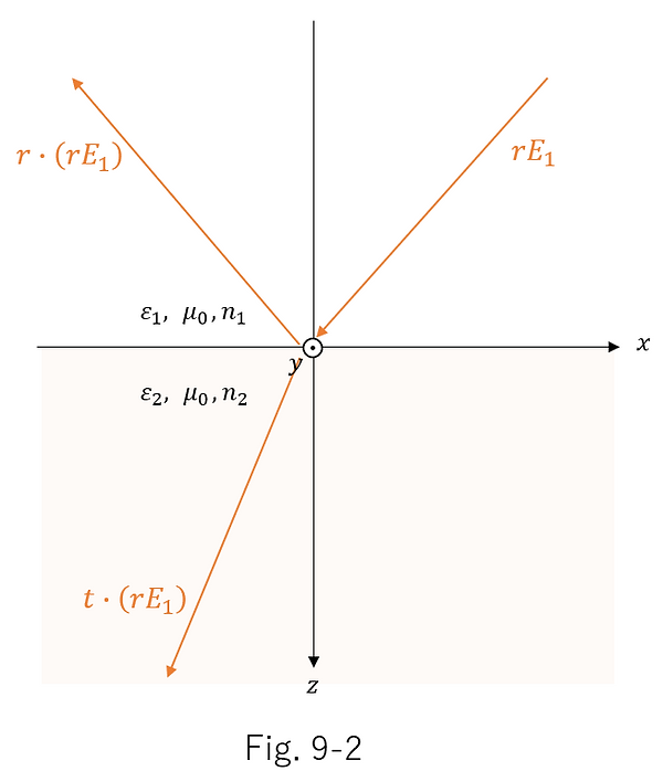
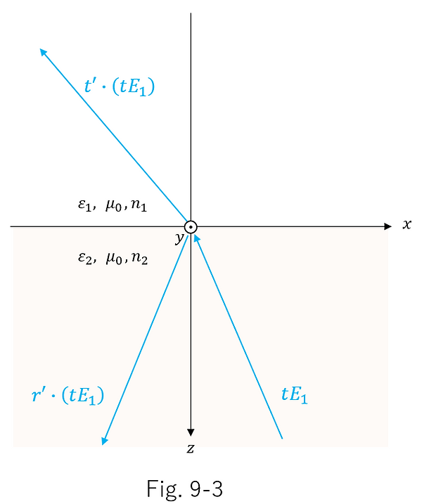
Furthermore, if the transmitted light in Figure 9-1 is directed in the opposite direction and incident on the interface again, the following electric field amplitude relationship in Figure 9-3 holds true.
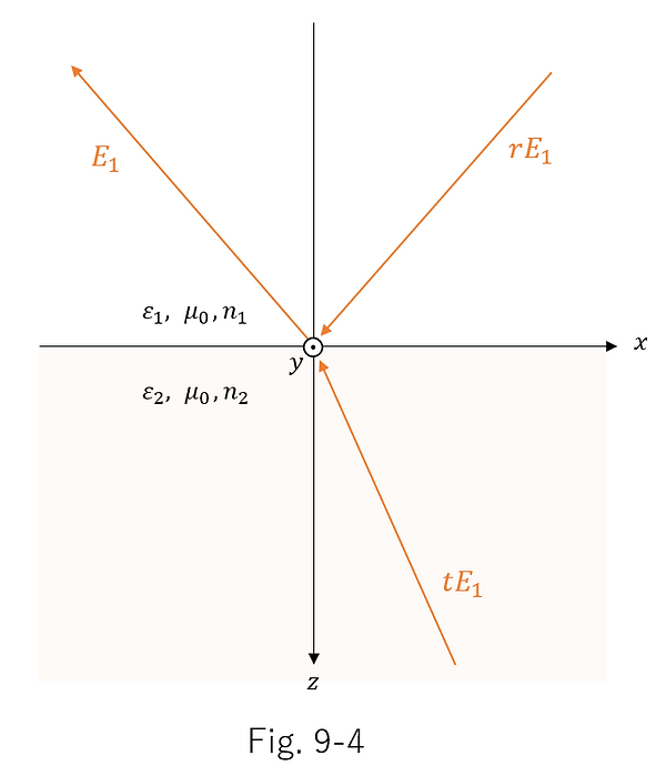
Also, if there is no absorption in the medium, the progression of light waves is reversible, so the following Figure 9-4 also holds true, in which the progression of all of the incident light, reflected light, and transmitted light in Figure 9-1 is reversed.
Here, Figure 9-5 below, which is a combination of Figures 9-2 and 9-3, has the same incident light as Figure 9-4, which means that the transmitted and reflected light should also be the same .

From this, the following equation holds:
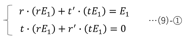
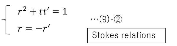
That is,
-
Postscript
Up to this point, we have derivated the equations for electromagnetic waves in non-absorbing media. Continuing on from this, we will now derive the equations for electromagnetic waves in absorbing media.
The signs of phase differ between physics and optics due to conventions. In this document, we use the conventions of physics; see below for differences between this and optics.
-
References
-
Related literature
[A] Shigenobu Sunagawa, Denzikigaku (Electromagnetism). Iwanami Shoten.
-
Update History
-
2026-04 Added "Description of elliptic polarization due to the p/s polarization component of electromagnetic waves incident on the interface".
-
2025-12 "Equation for electromagnetic waves in an absorbent medium" deleted (moved to a separate page)
-
2025-05 Newly released.