Electromagnetic wave theory of light reflection and refraction (II)
~Extension to absorbing media using complex refractive index~ …(EM2)
*This page is a continuation from the link below.
-
Equation for electromagnetic waves in absorbing media
From (EM1)-(2)-①, (EM1)-(2)-③, and (EM1)-(1)-④, the equation for electromagnetic waves can be expressed as follows:

Therefore,

Here, the refractive index n is expanded to a complex number, which allows us to express the effect of absorption by the medium mathematically.
In (10)-①, the refractive index n is replaced with the complex refractive index shown below.
*The definition of the sign of phase differs between the fields of physics and optics, according to their respective conventions. See (SG) for details.
Here, κ is called the extinction coefficient.
At this time,

Therefore, if the light intensity is I,

Here, the absorption coefficient α is defined as follows:

Applying this,

This means that the light intensity attenuates exponentially with respect to ek・r , and 1/α represents the depth in the direction of light wave propagation from r = 0 until the light intensity becomes 1/e times. This depth is called the absorption length and is used as a guide to the depth that light can penetrate.
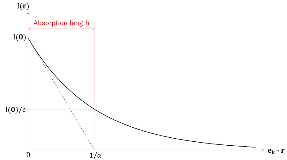
Furthermore, (10)-⑥ can be illustrated spatially as follows:

Here, for the sake of simplicity, ekz =0.
-
Application of Snell's law to absorbing media
The refractive index of medium 1 is n1, and the refractive index of medium 2 is n2. Also, with respect to the interface between medium 1 and medium 2, the incident angle from medium 1 is θ, and the outgoing angle to medium 2 is ξ.

Here, if medium 2 is an absorbing medium, the effect of absorption by medium 2 can be expressed mathematically by replacing the refractive index n2 with the complex refractive index below, as in (10)-②.
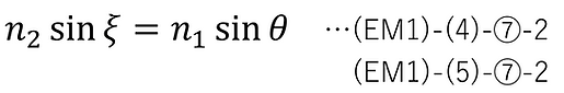
In this case, since the right-hand sides of (EM1)-(4)-⑦-2 and (EM1)-(5)-⑦-2 are real numbers, ξ must also be a complex number to satisfy the equation. This can be expressed as follows.
Here, the range of values for each parameter is determined as follows:

Replacing n2 and ξ in (EM1)-(4)-⑦-2 and (EM1)-(5)-⑦-2 with (11)-①-1 and (11)-①-2 respectively and rearranging the equations gives the following:

Here, from (11)-①-3 and (11)-②,
[ i ] When θ = 0,
ξr = ξi = 0
[ ii ] When θ ≠ 0,
Since ξr ≠ 0 and ξi ≠ 0,
・Derivation of ξi :
Transforming (11)-② gives us :

Here, the following is set:

Applying this to the above equation,
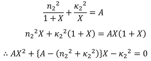
Since X > 0, A > 0,

Here, we put it as follows:

Applying this to the above equation,

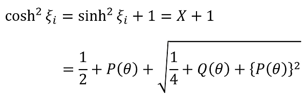
Here, from (11)-①-3 and (11)-②, the following can be said:

Therefore,

ξi can also be expressed as follows:
Here, from (11)-①-3 and (11)-②, the following can be said:

Therefore,

However, ξi < 0 (∵ (11)-③-5)
・Derivation of ξr :
Once again, transforming (11)-② gives us :

Here, we put it as follows:

Applying this together with (11)-③-1b shown previously to the above equation, we get

Since Y > 0, A > 0,

Again, applying (11)-③-2a,b,

Here, from (11)-①-3, the following can be said:

Therefore,

However, 0 < ξ r < π /2 (∵ (11)-①-3)
ξr can also be expressed as follows:

Here, from (11)-①-3, the following can be said:

Therefore,

However, 0 < ξ r < π /2 (∵ (11)-①-3)
·Summary
To summarize the above results,

… (11)-③-5,7, (11)-④-5,7

… (11)-③-2a,b
-
Application of Fresnel formula to absorbing media and energy reflectance.
[ i ] When θ=0,
At normal incidence, p-polarized light and s-polarized light are in the same state, so they are shown together.
The Fresnel formula for normal incidence (s,p polarization) derived in the previous chapter is shown below.

Here, by replacing the refractive index n2 with the complex numbers shown in (11)-①-1, the amplitude reflectance (s, p polarization) when incident on an absorbing medium can be expressed as follows:

Therefore, from (EM1)-(6)-④,⑦, the energy reflectance (s, p polarization) when incident on an absorbing medium is as follows:

[ii] When θ≠0,
・In the case of p-polarized light
The Fresnel formula (p-polarized light) derived in (EM1) is shown below.

Here, by replacing the refractive index n2 and the exit angle ξ with the complex numbers shown in (11)-①-1,2, the amplitude reflectance (p-polarized light) when incident on an absorbing medium can be expressed as follows:

When n2 >n1 , (12)-②-1 can be expressed as follows, separated into amplitude and phase (however, the rule of (CM) is applied).

*(12)-②-2b-r will be derived later.
Here, the blue parts in the equation represent cases where the value of θ+ ξr is zero when it is less than π /2, and -π when it is greater than π /2 (this is based on the definition of (CM) ).
Here, the amplitude reflectance (p-polarization) rp is defined as the ratio of the electric field amplitude Eip of the incident light to the electric field amplitude Erp of the reflected light, but the fact that the left side is a complex number means that at least one of the amplitudes of the electric field on the right side is a complex number (complex amplitude).

Also, from (EM1)-(6)-④, the energy reflectance (p-polarized light) when incident on an absorbing medium is as follows:

However, since ξr and ξi are given as functions of θ in (11)-③-5,7 and (11)-④-5,7, (12)-②-1,2,4 are also functions of θ.
・In the case of s-polarized light
The Fresnel formula (s-polarized light) derived in (EM1) is shown below.

Here, by replacing the refractive index n2 and the exit angle ξ with the complex numbers shown in (11)-①-1,2, the amplitude reflectance (s-polarized light) when incident on an absorbing medium can be expressed as follows:

When n2 >n1 , (12)-③-1 can be expressed as follows, separated into amplitude and phase (however, the rule of (CM) is applied) :

*(12)-③-2b-r will be derived later.
Here, the amplitude reflectance (s-polarization) rs is defined as the ratio of the electric field amplitude Eis of the incident light to the electric field amplitude Ers of the reflected light, but the fact that the left side is a complex number means that at least one of the amplitudes of the electric field on the right side is a complex number (complex amplitude).

Also, from (EM1)-(6)-⑦, the energy reflectance (s-polarized light) when incident on an absorbing medium is as follows:

However, since ξr and ξi are given as functions of θ in (11)-③-5,7 and (11)-④-5,7, (12)-③-1, 2, 4 are also functions of θ.
・Derivation of angle range
We will derive (12)-②-2b-r and (12)-③-2b-r.
First, from (11)-①-3 and θ≠0 and n2 >n1 ,

Also, from (11)-②,

From (12)-④-1,2, the following can be said.

From (12)-④-1,3, the following can also be said.

Therefore, (12)-②-2b-r and (12)-③-2b-r are shown.
・Case studies
If the refractive index of aluminum at a wavelength of 589.3 nm is 1.44 and the extinction coefficient is 5.23, the relationship between the incident angle θ and the energy reflectance when light is incident on aluminum from the air can be calculated using (12)-②,③-2, and the following graph is obtained.

It is important to note that in a non-absorbing medium, there is a Brewster angle, which is the angle at which the reflectance of p-polarized light becomes zero, but in an absorbing medium, there is no angle at which the reflectance becomes zero, so the Brewster angle cannot be defined in the sense of the angle at which the reflectance becomes zero.
-
Related Topics
Ellipsometry is an application of the principles described above to the non-destructive measurement of thin film thickness and complex refractive index. See below for the principles of ellipsometry.
Conventions for the signs of phase differ between physics and optics. Here we use the conventions of physics; see below for differences between this and optics.
For the method of calculating the absorption coefficient in (10)-⑤ from the actual transmittance measurement of the material, please refer to the following.
-
Related literature
[A] Shigenobu Sunagawa, Denzikigaku (Electromagnetism). Iwanami Shoten.
-
Update History
-
2026-03 "Derivation of the Definition of Ellipsometry" deleted (moved to a separate page)
-
2025-12 New release