
Transmission and Reflection Intensity in Two‑Interface Thin‑Film Interference: Derivation from the Electromagnetic Wave Equations
…(IT)
Interference intensity can be quantitatively described as the superposition of electromagnetic waves. This chapter starts from the fundamental equation for electromagnetic waves (EM1) and derives a general equation for the light intensity observed when multiple waves are superimposed. This general equation provides a unified explanation for a wide range of interference phenomena, from interference fringes (such as Newton's rings) that occur at interfaces with curvature to transmission and reflection intensity equations in thin-film interference dominated by multiple reflections at two interfaces. The purpose of this chapter is to understand the behavior of interference, which cannot be fully captured by apparent brightness alone, based on the electromagnetic wave equation.
Furthermore, this page clarifies the difference between rigorous theories based on physical principles and the abstractions in thin-film design theory that are reconstructed based on those theories, offering a perspective not found in conventional explanations that often confuse the two.
table of contents:
-
Two-interface thin-film interference in the normal incidence approximation
・ Two-interface thin-film interference in the normal incidence approximation derived from the electromagnetic wave equation
Based on the electromagnetic wave equation (EM1) , we derive the two-interface interference under the normal incidence approximation. First, the system model is shown below.

however,
-
With respect to the z-axis, the region from -∞ to 0 is defined as medium 1, the region from 0 to d as medium 2, and the region from d to +∞ as medium 3.
-
Assume there is no absorption in each medium.
-
The incident light travels from z=-∞ in the +z direction and enters medium 2.
-
Let Ei be the electric field vector of the incident light, Et be the electric field vector of the transmitted light, and Er be the electric field vector of the reflected light.
-
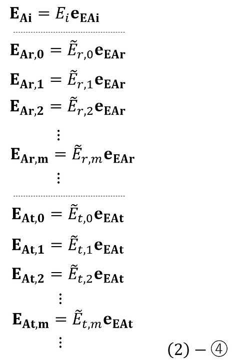
The electric field vector of transmitted light is given as the sum of the electric field components corresponding to each transmission order in multiple reflections, and each component is represented by Et,m (where m is the number of reflections at the medium 2–3 interface).
Furthermore, the electric field vector of the reflected light is given as the sum of the electric field components corresponding to each reflection order in multiple reflections, and each component is represented by Er,m (where m is the number of reflections at the medium 2–3 interface).
This can be expressed as follows:

-
Transmission and reflection occur at the interface between medium 1 and 2, and at the interface between medium 2 and 3, respectively. The amplitude transmittance and amplitude reflectance at each surface are expressed as follows.
・When incident from medium 1 to medium 2,
Amplitude transmission: t12
Amplitude reflectance: r12
・When incident from medium 2 to medium 1,
Amplitude transmission: t'12
Amplitude reflectance: r'12
・When incident from medium 2 to medium 3,
Amplitude transmission: t23
Amplitude reflectance: r23
-
Let k1 , k2 , and k3 be the wavenumbers of light in media 1, 2, and 3, and let ω be the angular frequency.
The electric field vectors of the incident and reflected light are expressed as follows:

however,
-
The electric field amplitude vector of the incident light is EAi
-
EAt,m is the electric field amplitude vector of the transmitted light component corresponding to each transmission order in multiple reflections (where m is the number of reflections at the medium 2–3 interface).
-
EAr,m is the electric field amplitude vector of the reflected light component corresponding to each reflection order in multiple reflections (where m is the number of reflections at the medium 2–3 interface).
Let's assume that.
Here, the amplitude vector of the electric field is expressed as the product of the amplitude (scalar quantity) and the unit direction vector eEA , as follows.

Substituting (1)-③ into (1)-② yields the following:

Substituting (1)-②' into (1)-① yields the following:

Here, we set it as follows:

Substituting this into (1)-①', we get the following:

Here, all changes in amplitude and phase that occur from just before the electric field is incident on the interface between medium 1 and medium 2 until just after it exits in the +z and -z directions after multiple reflections at the interface are included in the amplitude vectors of the transmitted and reflected light components corresponding to each transmission and reflection order. In this case, each amplitude is expressed as follows.

Here, from Stokes' relation ( (EM1)-(9)-② ), the following can be said.

Substituting (1)-⑥ into (1)-⑤, we get the following:

Substituting this into (1)-④ and rearranging, we get the following:

Therefore, the amplitude reflectance r and amplitude transmittance t of the entire system are as follows.

From (EM1)-(6)-④ , the energy reflectance and energy transmittance can be calculated as follows.

Here, if we denote the refractive indices of media 1, 2, and 3 as n1 , n2 , and n3 , then according to Fresnel's law ( (EM1)-(4)-⑨'c, (EM1)-(5)-⑨'c ), the amplitude reflectance and amplitude transmittance at each interface can be expressed as follows using the refractive index of each medium.

The law of conservation of energy can be confirmed by calculating the sum of the energy reflectance and energy transmittance as follows .

Here, from (1)-⑩,

Therefore, the numerator and denominator of (1)-⑨ are equal,

・Complex plane representation of film thickness change and intensity change in two-interface thin film interference
From here on, we will focus solely on reflected light and consider the light intensity distribution resulting from interference.
If the amount of reflected light is Ir , then Ir is proportional to the square of the absolute value of the electric field vector of the reflected light, and can be calculated as follows.

If we let the wavelength in a vacuum be λ0, then k2 = 2πn2 / λ0,

The conditions for maximum and minimum interference between two interfaces can be reversed depending on the refractive index relationship of the medium. This reversal is difficult to grasp intuitively from the equations alone unless one understands how the phase change that occurs with each reflection affects the direction of the amplitude.
Therefore, by representing the reflection amplitude as a vector on the complex plane and geometrically tracking the change in its direction, we can intuitively follow the reversal of the interference conditions.
Therefore, from here on, we will find the trajectory on the complex plane for the reflection component of (1)-④', with d as the variable.
First, we find the standard form of the reflection component of (1)-④' as follows.

Therefore, if we let h be the center of the locus of a circle on the complex plane and R be the radius of curvature, then the following holds.

Here, from the reflection component of (1)-④' and (1)-⑬, the following relationship is obtained.

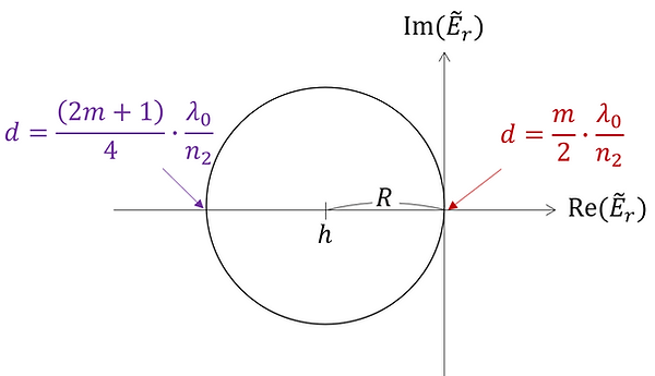
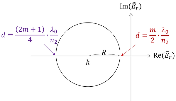
From the above, the circular locus on the complex plane can be obtained as follows. This circular locus represents the phase rotation of the reflection amplitude with respect to the change in film thickness d, and the conditions for the maximum and minimum of the reflection intensity can be understood geometrically.
(i)

At that time,

(ii)

At that time,

(iii)

At that time,

(iv)

At that time,

(v)

At that time,

(vi)

At that time,

(vii)

At that time,

(viii)

At that time,

(ix)

At that time,
(x)

At that time,

(xi)

At that time,
(xii)

At that time,

From the above, we can conclude the following:
-
When the refractive index of medium 2 is higher than that of mediums 1 and 3, or lower than that of mediums 1 and 3,
・When d = mλ0/2n2, the intensity is minimal (especially when n1 = n3 , the intensity is zero).
・When d = (2m + 1)λ0/4n2, the intensity is at its maximum.
-
When the refractive index of medium 2 is higher than that of medium 1 and lower than that of medium 3, or higher than that of medium 3 and lower than that of medium 1,
・When d = mλ0/2n2, the intensity is at its maximum.
・When d = (2m + 1)λ0/4n2, the intensity is minimal.
Understanding this point allows us to determine, for example, the conditions under which the center of Newton's rings [1] becomes brighter and the conditions under which it becomes darker. Normally, in Newton's rings, medium 2 is air, so its refractive index is lower than that of mediums 1 and 3, and if they are in contact at the center, the center will be darker. This behavior is illustrated below.
・Example: Interference intensity distribution in Newton's rings
As an example to show how an understanding of amplitude in the complex plane relates to actual interference fringes, we will consider Newton's rings. As shown in the figure below, consider the case where medium 1 has a gentle curvature with radius R and is in contact with medium 3 at x=0.

In this case, d can be expressed as a function of x as follows:

Furthermore, under the condition that interference occurs (i.e., when the thickness of medium 2 is on the order of the wavelength), the relation 𝑥≪𝑅 holds, and therefore the following approximation is generally applied.

Here, we set the parameters as follows:
n1=1.5
n2=1
n3 = 1.5
λ0 = 0.00055 mm
R=10000mm
In this case, from (1)-⑩, (1)-⑪', and (1)-⑮, the light intensity distribution with respect to x is represented as shown in the graph below, and since this corresponds to case (ix) in the complex plane, the values of d at the local maximum and minimum can also be indicated in the graph as follows.

Up to this point, we have dealt with the case of perpendicular incidence for the sake of simplicity, but in actual optical phenomena, it is more common to consider oblique incidence. Therefore, in the next section, we will deal with the case of oblique incidence (s-polarization and p-polarization).
-
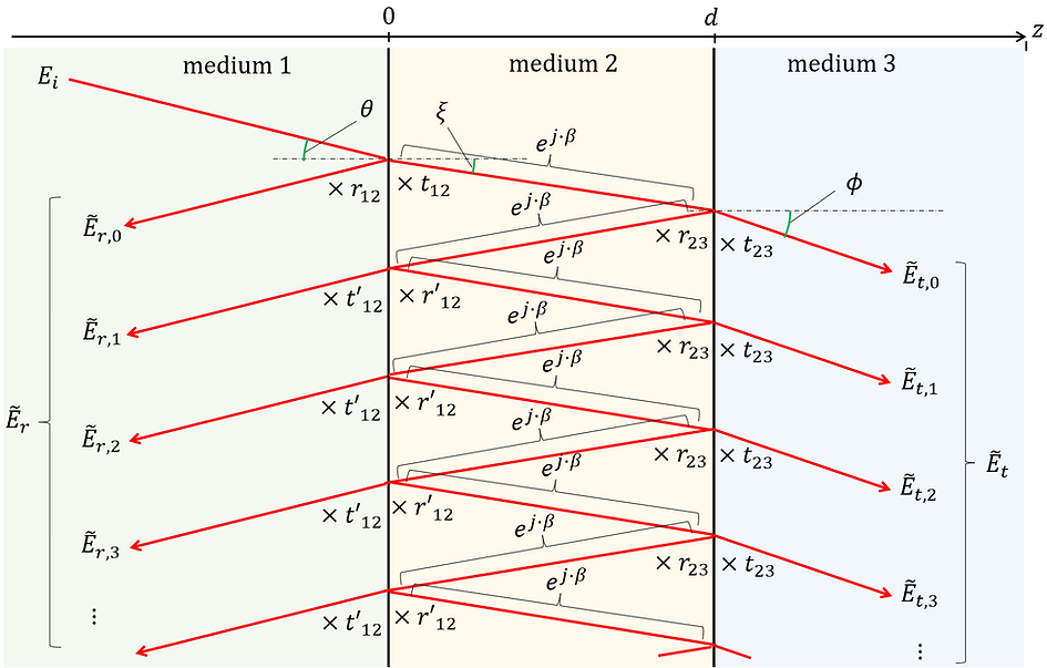
Two-interface thin-film interference in the oblique incidence
Here, we derive the two-interface interference under oblique incidence based on the electromagnetic wave equation (EM1) . The system model is shown again below.
First, the reflected light from each surface is illustrated as follows.

Similarly, the transmitted light from each surface is illustrated as follows.

however,
-
With respect to the z-axis, the region from -∞ to 0 is defined as medium 1, the region from 0 to d as medium 2, and the region from d to +∞ as medium 3.
-
Let O be the origin of the position vector.
-
Assume there is no absorption in each medium.
-
The incident light travels from z=-∞ in the +z direction and enters medium 2.
-
Let Ei be the electric field vector of the incident light, Et be the electric field vector of the transmitted light, and Er be the electric field vector of the reflected light. These electric fields are treated as either p-polarized or s-polarized (any polarization can be decomposed into p and s components, so they can be treated independently).
-
The electric field vector of transmitted light is given as the sum of the electric field components corresponding to each transmission order in multiple reflections, and each component is represented by Et,m (where m is the number of reflections at the medium 2–3 interface).
Furthermore, the electric field vector of the reflected light is given as the sum of the electric field components corresponding to each reflection order in multiple reflections, and each component is represented by Er,m (where m is the number of reflections at the medium 2–3 interface).
This can be expressed as follows:

-
Transmission and reflection occur at the interface between medium 1 and 2, and at the interface between medium 2 and 3, respectively. The amplitude transmittance and amplitude reflectance at each surface are expressed as follows.
・When incident from medium 1 to medium 2,
Amplitude transmission: t12
Amplitude reflectance: r12
・When incident from medium 2 to medium 1,
Amplitude transmission: t'12
Amplitude reflectance: r'12
・When incident from medium 2 to medium 3,
Amplitude transmission: t23
Amplitude reflectance: r23
-
Let k1 , k2 , and k3 be the wavenumbers of light in media 1, 2, and 3, and let ω be the angular frequency.
l1,m and l2 in the figure are represented as follows.

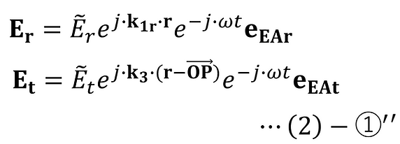
The electric field vectors of the incident and reflected light are expressed as follows:

however,
-
The electric field amplitude vector of the incident light is EAi
-
EAt,m is the electric field amplitude vector of the transmitted light component corresponding to each transmission order in multiple reflections (where m is the number of reflections at the medium 2–3 interface).
-
EAr,m is the electric field amplitude vector of the reflected light component corresponding to each reflection order in multiple reflections (where m is the number of reflections at the medium 2–3 interface).
Let's assume that.
Here, the amplitude vector of the electric field is expressed as the product of the amplitude (scalar quantity) and the unit direction vector eEA , as follows.
Substituting (2)-④ into (2)-③ yields the following:

Substituting (2)-③' into (2)-① yields the following:

Here, we set it as follows:

Substituting this into (2)-①', we get the following:
Here, all changes in amplitude and phase that occur from just before the electric field is incident on the interface between medium 1 and medium 2 until just after it exits in the +z and -z directions after multiple reflections at the interface are included in the amplitude vectors of the transmitted and reflected light components corresponding to each transmission and reflection order. In this case, each amplitude is expressed as follows.

From Stokes' relation ( (EM1)-(9)-② ), the properties of wavenumbers ( (EM1)-(1)-⑥ ), and Snell's laws ( (EM1)-(4)-⑦-2, (EM1)-(5)-⑦-2 ), the following can be said.

Furthermore, calculating the exponents of each equation (2)-⑥ yields the following:

However, from (2)-7d, cosξ can be expressed in terms of the angle of incidence θ as follows.

Substituting (2)-⑦ and ⑧ into (2)-⑥, we get the following:

Substituting this into (2)-⑤ and rearranging, we get the following:

Therefore, the amplitude reflectance r and amplitude transmittance t of the entire system are as follows [2] .

From (EM1)-(6)-④ , the energy reflectance and energy transmittance can be calculated as follows.

Here, if we denote the refractive indices of media 1, 2, and 3 as n1 , n2 , and n3 , then according to Fresnel's law ( (EM1)-(4)-⑨'c, (EM1)-(5)-⑨'c ), the amplitude reflectance and amplitude transmittance at each interface can be expressed as follows using the refractive index of each medium.
-
If each field vector is p-polarized:

-
If each field vector is s-polarized:

The derivations based on the electromagnetic wave equations presented so far provide a solid foundation for development into engineering applications such as multilayer analysis and optical thin film design. The theoretical framework established in this chapter provides a foundation for systematically and quantitatively understanding the behavior of optical thin films. These insights will serve as important guidelines for performance optimization and functional creation in actual device design and optical system development.
-
Development from the physics of thin-film interference to thin-film design theory
Based on the physical principles of thin-film interference that we have derived so far, we will now describe the thin-film design theory that is built upon these principles.
In actual physics, the difference in optical path length of wavefronts traveling at an angle is calculated directly. However, in thin-film design theory, by introducing a hypothetical optical distance called phase thickness, the geometric distance difference of light rays traveling within the film can be treated directly as a phase difference. This abstraction greatly simplifies the discussion of interference and provides a powerful framework for systematically advancing the analysis of multilayer films.
The system model is shown below.
however,
-
With respect to the z-axis, the region from -∞ to 0 is defined as medium 1, the region from 0 to d as medium 2, and the region from d to +∞ as medium 3.
-
Assume there is no absorption in each medium.
-
The incident light travels from z=-∞ in the +z direction and enters medium 2.
-
The complex amplitude of the electric field of transmitted light is given as the sum of the electric field components corresponding to each transmission order in multiple reflections, and each component is represented by Et,m (where m is the number of reflections at the medium 2–3 interface).
Furthermore, the complex amplitude of the electric field of the reflected light is given as the sum of the electric field components corresponding to each reflection order in multiple reflections, and each component is represented by Er,m (where m is the number of reflections at the medium 2–3 interface).
This can be expressed as follows:

-
Transmission and reflection occur at the interface between medium 1 and 2, and at the interface between medium 2 and 3, respectively. The amplitude transmittance and amplitude reflectance at each surface are expressed as follows.
・When incident from medium 1 to medium 2,
Amplitude transmission: t12
Amplitude reflectance: r12
・When incident from medium 2 to medium 1,
Amplitude transmission: t'12
Amplitude reflectance: r'12
・When incident from medium 2 to medium 3,
Amplitude transmission: t23
Amplitude reflectance: r23
-
Let k1 , k2 , and k3 be the wavenumbers of light in media 1, 2, and 3, and let ω be the angular frequency.
Thus, in this context, the electric field is treated as a complex amplitude (scalar quantity) from the outset. Furthermore, in thin-film design theory, the phase film thickness δ shown below is defined.

However, according to Snell's Law,

β is a phase quantity corresponding to the phase film thickness δ, and is expressed as follows:

The phase film thickness δ introduced for one-way propagation between the interface of medium 1–2 and the interface of medium 2–3 is defined as a hypothetical optical distance to simplify the analysis of multiple reflections. Therefore, this δ does not coincide with the optical distance n2 l2 = n2 d / cosξ based on the actual optical path length.
On the other hand, in the physical derivation (Equation (2)-⑥'), the phase of the complex amplitude of the electric field changes by 2β each time light travels back and forth between the interface surfaces. However, this 2β does not correspond to the round-trip distance between the films themselves, but rather to the fact that the difference in optical path length that occurs when the same phase surface is used as a reference is 2δ.
Therefore, in order to systematically organize the analysis, we introduce a hypothetical representation that assumes one-way propagation between films travels an optical distance δ. This virtualization allows us to formally treat the phase change 2β corresponding to the round trip distance 2δ between the films as a quantity corresponding to the round trip distance 2δ, thereby significantly simplifying the description of multiple reflections.
Furthermore, from Stokes' relation ( (EM1)-(9)-② ),

When the above is applied, the complex amplitude of the electric field is expressed as follows.

Substituting this into (3)-①', the complex amplitudes of transmission and reflection for the entire system are obtained as follows.

Therefore, the amplitude reflectance and amplitude transmittance of the entire system are obtained as follows.

The phase term included in the numerator of t does not coincide with the phase in equation (2)-⑨ derived from physical principles. This is because the phase film thickness δ = n2 d cosξ, which corresponds to the phase β included in Et,0 in (3)-⑤, is different from the optical distance n2 l2 = n2 d / cosξ, which is based on the actual optical path length that appears in Et,0 in (2)-⑥'. However, since the phase of the molecule does not contribute to the energy transmittance T, as shown below, this difference does not affect the results in thin film design. Therefore, the abstractions used in thin film design theory are not inconsistent with actual physical principles and can be said to be theoretically consistent.

The foundations of thin-film design theory developed in this chapter provide a solid basis for quantitatively understanding the properties of optical thin films and applying them to actual device design and optical system development. The theoretical framework established here is essential for optimizing the performance of various optical elements, including anti-reflective coatings and interference filters, and plays an important role as a guideline for design and analysis in optical engineering.
-
References
[2] Saikai, Junichi. Fundamentals of Optics. Corona Publishing Co., Ltd., 1997.
-
Related literature
[A] Inoue, K. & Nakajima, S., Optics, Kyoritsu Publishing
[B] Tanaka, T., Introduction to Optics, Shokabo Publishing
[C]Max Born & Emil Wolf, Principles of Optics, Cambridge University Press
-
Update History
-
2026-06 Added "Two-interface thin-film interference in the oblique incidence" .
-
2026-06 Newly released.