
F‑Number in Imaging Optical Systems
~ Geometrical Optics Derivation of Pupil Magnification and Effective F‑Number ~ …(FN)
The F-number of an imaging optical system is a crucial parameter that affects image quality and illumination. This page organizes the geometrical optical definition along with ray diagrams and summarizes the relationships between related parameters from a practical perspective.
This page will proceed with the discussion based on the following rules.
Rule A: Dimensions and angle notation
Dimensions and angles are indicated in Appendix: Following the definitions of dimensions and angles on this site , a single-sided arrow with direction is considered positive for vertical directions (upward), rightward for horizontal directions, and counterclockwise for rotation (counterclockwise is negative). Quantities indicated by double-sided arrows without direction are always treated as positive values.
Rule B: Definition of the paraxial region
All rays discussed on this page are assumed to be paraxial rays with sufficiently small angles. That is, when the angle is θ, the following approximation is applied:
sin θ = θ, tan θ = θ, cos θ = 1
・Geometric optical definition of the F-number of an imaging optical system and derivation of the related formulas.
In imaging optical systems, the F-number (or F-value) is a fundamental parameter that influences many performance elements, such as illumination, image quality, depth of field, and noise characteristics. However, in imaging systems, the effective F-number is determined not only by the F-number of the lens itself, but also by several geometric optical quantities such as the entrance pupil position, exit pupil position, magnification, and image-side distance. This page begins with the definition of the F-number in imaging optical systems ( (BS)-(3)-①a ) and systematically derives the relationships between related parameters using ray diagrams.
Here, if we superimpose the light rays entering the entrance pupil and exiting the exit pupil with the other major light rays, the diagram will look like this.
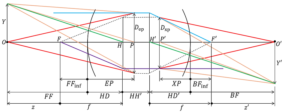
*Apply Rule A (Symbol Convention) and Rule B (Definition of Paraxial Region).
*However, Dep and Dxp are treated as positive values without direction.
however,
f: focal length
z: object distance
z': Image distance
EP: Entrance pupil position
XP: Exit pupil position
HD: Front principal point position
HD': Back principal point position
HH': Distance between principal points
FFinf : Front focal position
BFinf : Back focal position
For the derivation of these optical system parameters, please refer to (PX) .
First, we define the F-number as follows:
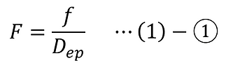
At this point, the following can be said:

Furthermore, pupillary magnification is defined as follows:
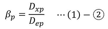
At this point, the following can be said:
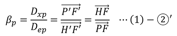
This can be expressed using the following optical parameters.

Furthermore, the lateral magnification is defined as follows:
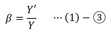
At this point, from Newton's formula, we can say the following ( (IG)-(1)-⑨c ).

Here, the effective F number is defined as follows:
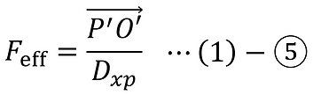
At this point, applying the equations ((1)-①,②,②'',④) shown so far, the effective F-number can be expressed using the lateral magnification, pupillary magnification, and F-number as follows.

The lateral magnification β is a quantity that changes depending on the object position and image position. On the other hand, the entrance pupil diameter and exit pupil diameter are constant, independent of the object position and image position, when the optical system is paraxial and fixed. Therefore, pupil magnification can also be treated as a constant that is not affected by the object position or image position.
-
Calculation format
The Excel format for calculating pupil magnification and effective F-number, as shown above, is provided below.
Please note that the following format is on a separate page (PX) This also includes the calculation of optical system parameters based on ray propagation derived from paraxial calculations in a spherical lens system .
Furthermore, the following format also includes the calculation of optical system parameters based on ray propagation derived from the Gaussian imaging equation in an ideal lens system, as shown on a separate page (IG) .
-
References
[1] Kishikawa, Toshiro. Yūzā Enjinia no Tame no Kōgaku Nyūmon (An Introduction to Optics for User Engineers). Optronics Co.
[2] Tomowaki Takahashi, "Lens Design: From Aberration Coefficients to Automated Design," Tokai University Press.
-
Update History
-
2026-07: Newly released